- 您现在的位置:买卖IC网 > Sheet目录346 > NCP5010FCT1G (ON Semiconductor)IC LED DRVR WHT BCKLT 8-FLIPCHIP
�� �
�
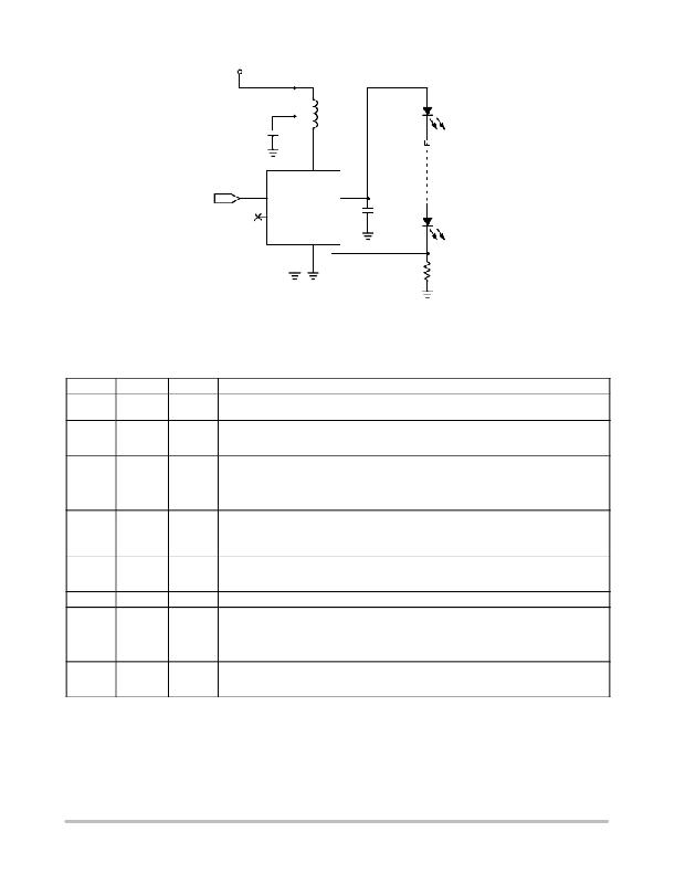
NCP5010�
�V� bat�
�2.7� to� 5.5� V�
�C� in�
�4.7� m� F� 0603�
�X5R� 6.3V�
�L1�
�22� m� H�
�LED�
�ENABLE�
�A2�
�A3�
�CTRL�
�NC�
�V� OUT�
�C1�
�C� out�
�1� m� F� 0805�
�X5R� 25V�
�LED�
�NCP5010�
�R� fb�
�24�
�Figure� 2.� Typical� Application� Circuit�
�PIN� FUNCTION� DESCRIPTION�
�PIN�
�A1�
�PIN� NAME�
�AGND�
�TYPE�
�POWER�
�DESCRIPTION�
�System� ground� for� the� analog� circuitry.� A� high� quality� ground� must� be� provided� to� avoid� spikes� and/�
�or� uncontrolled� operations.� This� pin� is� to� be� connected� to� the� PGND� pin.�
�B1�
�V� IN�
�POWER�
�Power� Supply� Input.� A� ceramic� capacitor� with� a� minimum� value� of� 1� m� F/6.3� V� (X5R� or� X7R)� must� be�
�connected� to� this� pin.� This� capacitor� should� be� placed� as� close� as� possible� to� this� pin.� In� addition,�
�one� end� of� the� external� inductor� is� to� be� connected� at� this� point.�
�C1�
�V� OUT�
�POWER�
�DC?DC� converter� output.� This� pin� should� be� directly� connected� to� the� load� and� a� low� ESR�
�(<30� m� W� )� 1� m� F� (min)� 25� V� bypass� capacitor.� This� capacitor� is� required� to� smooth� the� current� flowing�
�into� the� load,� thus� limiting� the� noise� created� by� the� fast� transients� present� in� this� circuit.� Since� this� is�
�a� current� regulated� output,� this� pin� has� over� voltage� protection� to� protect� from� open� load� conditions.�
�Care� must� be� taken� to� avoid� EMI� through� the� PCB� copper� tracks� connected� to� this� pin.�
�A2�
�CTRL�
�INPUT�
�An� Active� High� logic� level� on� this� pin� enables� the� device.� A� built?in� pulldown� resistor� disables� the�
�device� if� the� pin� is� left� open.� This� pin� can� also� be� used� to� control� the� average� current� into� the� load�
�by� applying� a� low� frequency� PWM� signal.� If� a� PWM� signal� is� applied,� the� frequency� should� be� high�
�enough� to� avoid� optical� flicker� but� be� no� greater� than� 1� kHz.�
�C2�
�SW�
�POWER�
�Power� switch� connection� for� inductor.� Typical� application� will� use� a� coil� from� 10� m� H� to� 22� m� H� and�
�must� be� able� to� handle� at� least� 350� mA.� If� the� desired� output� power� is� above� 300� mW,� the� inductor�
�should� have� a� DCR� <� 1.4� W� .�
�A3�
�B3�
�NC�
�FB�
�N/A�
�INPUT�
�Not� Connected�
�Feedback� voltage� input� used� to� close� the� loop� by� means� of� a� sense� resistor� connected� between� the�
�primary� LED� branch� and� the� ground.� The� output� current� tolerance� is� depends� upon� the� accuracy� of�
�this� resistor� and� a� ±� 5%� or� better� accuracy� metal� film� resistor� is� recommended.� An� analog� dimming�
�signal� can� be� applied� to� this� point� to� reduce� the� output� current.� Please� refer� to� the� application�
�section� for� additional� details.�
�C3�
�PGND�
�POWER�
�Power� ground.� A� high� quality� ground� must� be� used� to� avoid� spikes� and/or� uncontrolled� operation.�
�Care� must� be� taken� to� avoid� high?density� current� flow� in� a� limited� PCB� copper� track.� This� pin� is� to�
�be� connected� to� the� AGND� pin.�
�http://onsemi.com�
�2�
�发布紧急采购,3分钟左右您将得到回复。
相关PDF资料
NCP5021MUTXG
IC WHITE LED DVR HV AMB 16-UQFN
NCP5050MTTXG
IC LED DRIVR PHOTO FLASH 10-WDFN
NCP5111DR2G
IC DRIVER HI/LOW SIDE HV 8-SOIC
NCP5304DR2G
IC DRIVER HI/LOW SIDE HV 8-SOIC
NCP5355DG
IC DRVR SYNC BUCK MOSF 12A 8SOIC
NCP5359ADR2G
IC MOSFET GATE DVR DUAL 8-SOIC
NCP5359DR2G
IC GATE DRIVER VR11.1/AMD 8-SOIC
NCP5360RMNR2G
IC DRIVER MOSFET 56QFN
相关代理商/技术参数
NCP502
制造商:ONSEMI 制造商全称:ON Semiconductor 功能描述:80 mA CMOS Low Iq Voltage Regulator in an SC70−5
NCP502 K20PA WAF
制造商:ON Semiconductor 功能描述:
NCP502/D
制造商:未知厂家 制造商全称:未知厂家 功能描述:80 mA CMOS Low Iq Voltage Regulator in an SC70-5
NCP502_07
制造商:ONSEMI 制造商全称:ON Semiconductor 功能描述:80 mA CMOS Low Iq, Low−Dropout Voltage Regulator
NCP5021
制造商:ONSEMI 制造商全称:ON Semiconductor 功能描述:High Voltage White LED Driver with Ambient Light Sensing
NCP5021MUTXG
功能描述:低压差稳压器 - LDO NCP5021 RoHS:否 制造商:Texas Instruments 最大输入电压:36 V 输出电压:1.4 V to 20.5 V 回动电压(最大值):307 mV 输出电流:1 A 负载调节:0.3 % 输出端数量: 输出类型:Fixed 最大工作温度:+ 125 C 安装风格:SMD/SMT 封装 / 箱体:VQFN-20
NCP502ASQ15T1
制造商:ONSEMI 制造商全称:ON Semiconductor 功能描述:80 mA CMOS Low Iq Voltage Regulator in an SC70−5
NCP502ASQ15T1G
制造商:ONSEMI 制造商全称:ON Semiconductor 功能描述:80 mA CMOS Low Iq, Low−Dropout Voltage Regulator